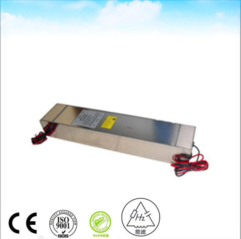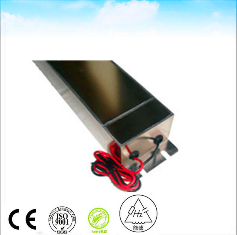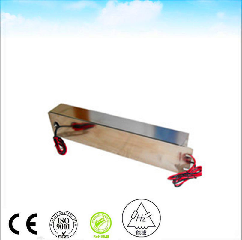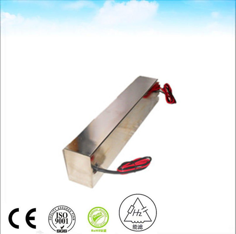
250V 16A Rfi Ac Emi Power Line Filters Ac Voltage Filter Emi Emc Filter Design
-
Highlight
16A Emi Rfi Ac Power Line Filters
,250V Emi Rfi Ac Power Line Filters
,250Vac power line noise filter
-
TypeEMI Filter
-
Transfer FunctionLow Pass
-
Package TypeThrought Hole
-
Nominal Center Frequency50/60Hz
-
3dB Bandwidth14K
-
Insertion Loss100dB
-
Input Impedance50ohm
-
Stopband Attenuation100dB
-
Rated Voltage120/250VAC
-
Rated Current16A 30A
-
Operating Frequency50/60Hz
-
ApplicationRf Shielding Room
-
PortShanghai
-
Place of OriginChina
-
Brand Namenenglv
-
Certificationce
-
Model NumberHZ-2X16C5
-
Minimum Order Quantity>=1 Pieces
-
Price$200.00
-
Packaging Details1 pcs in one carton the gross weight is about 20Kg
-
Supply Ability100 Piece/Pieces per Week
250V 16A Rfi Ac Emi Power Line Filters Ac Voltage Filter Emi Emc Filter Design
250VAC 16A emi power line filter rf shielding
How does an input EMI filter work?
Most electronics contains an EMI filter, either as a separate device, or embedded in circuit boards. Its function is to reduce high frequency electronic noise that may cause interference with other devices. Regulatory standards exist in most countries that limit the amount of noise that can emitted.
EMI, or Electro-Magnetic Interference, is defined as unwanted electrical signals and can be in the form of conducted or radiated emissions. Conducted EMI is where the noise travels along the electrical conductors and radiated EMI is where the noise travels through the air as magnetic fields or radio waves.
EMI is generated from the switching of electrical current and comes from a variety of sources including electronic power supplies. Power supplies convert an input voltage into regulated and isolated (in most cases) DC voltages to run a host of electronic components. That conversion is performed at high frequencies ranging from several kHz to more than a MHz. LED lighting, computers, motor drivers, DC relays and battery chargers all rely on power supplies to operate.
An EMI filter for a power supply normally consists of passive components, including capacitors and inductors, connected together to form LC circuits. The inductor(s) allow DC or low frequency currents to pass through, while blocking the harmful unwanted high frequency currents. The capacitors provide a low impedance path to divert the high frequency noise away from the input of the filter, either back into the power supply, or into the ground connection.
In addition to assisting to meet EMI regulations, the filter also has to meet safety standards. The inductor temperature rise is measured and for mains operation, the minimum electrical spacing between line, neutral and ground are controlled. This reduces the risk of fire and electrical shock. The capacitors are also individually safety certified, depending on their position in the circuit. Special “X” capacitors have to be used across the input terminals and “Y” capacitors from the AC circuit to ground.
| RATED VOLTAGE | 250 VAC | ||
| RATED CURRENT | 30 A | ||
| OPERATIONAL FREQUENCY | 50 60 Hz | ||
| Voltage Drop | Less than 1V | ||
| Overload | 140% of rated current for 15 minutes | ||
| Harmonic Distortion | Less than 2% @ full rated current | ||
| Leakage Current | ≤0.2A@380/230VAC and 50Hz | ||
| Dielectric Withstanding Voltage | 1000VDC (line to line) 1000VDC (line to case) | ||
| DC Insulation Resistance | As Per MIL-STD-202 Method 202 | ||
| Terminal Strength | As Per MIL-STD-202 Method 211 | ||
| Temperature Rise | As Per MIL-F-15733 | ||
| Insertion Loss | ≥100dB@14K-40GHz As Per MIL-STD-220A, Under Load Condition | ||
| Climatic Classification | 25/070/21 | ||
Our technical service team learn many kinds of test standard such as industrial application (IEC61800-3 for frequency inverter drive EN12015 for elevator EN55011 for ISM device etc) and military application (GJB151A GJB152A etc).We can solve EMI problem quickly effectively and low-costly.

